



How to Verify 5-Axis CNC Accuracy for Stainless Steel 304 Milling to ±0.05mm
Published on Wednesday, 22. July 2026

Content Guide:Optimize 5-axis CNC machining for stainless steel (304) to achieve ±0.05mm precision. This guide details a systematic verification workflow covering machine geometric accuracy, tool runout calibration, CAM simulation, and CMM-based witness sample inspection. Ensure reliable mass production with comp
I. Introduction
The application of 5-axis CNC machining is increasingly widespread in fields such as aerospace, medical devices, and mold manufacturing, particularly in milling operations on stainless steel (304) materials. How to ensure parts meet general precision requirements of ±0.05mm through systematic process capability verification and accuracy assurance standards has become a core skill that process engineers must master. This document aims to provide process engineers with an executable derivation workflow and practical standards.
II. Core Verification Modules
1. Machine Tool Geometric Accuracy Verification
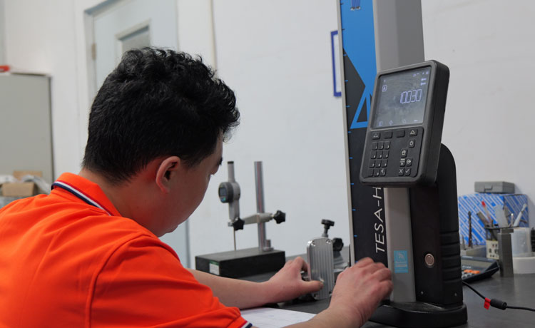
Before formal production, the spindle radial/axial runout, rotary table positioning accuracy, and linear axis backlash should be inspected. Use a laser interferometer and dial indicator to perform dynamic tests, record deviation values, and implement pitch error compensation. It is recommended to control the actual measured runout within 0.01mm, serving as the baseline for subsequent tool deviation correction.
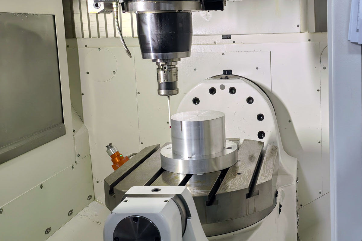
5-Axis Basic Accuracy Inspection
2. Tool and Clamping System Verification
After selecting the tool and hydraulic chuck, use a coaxiality measuring instrument to check tool runout after clamping. For milling 304 stainless steel, the coaxiality between the face mill and the tool holder should be within 0.02mm. Simultaneously replace with new inserts and, after pre-tightening the torque to a stable value, retain a trial-cut sample for tool wear testing. If dimensional stability is achieved after three trial cuts, the clamping system is considered verified.
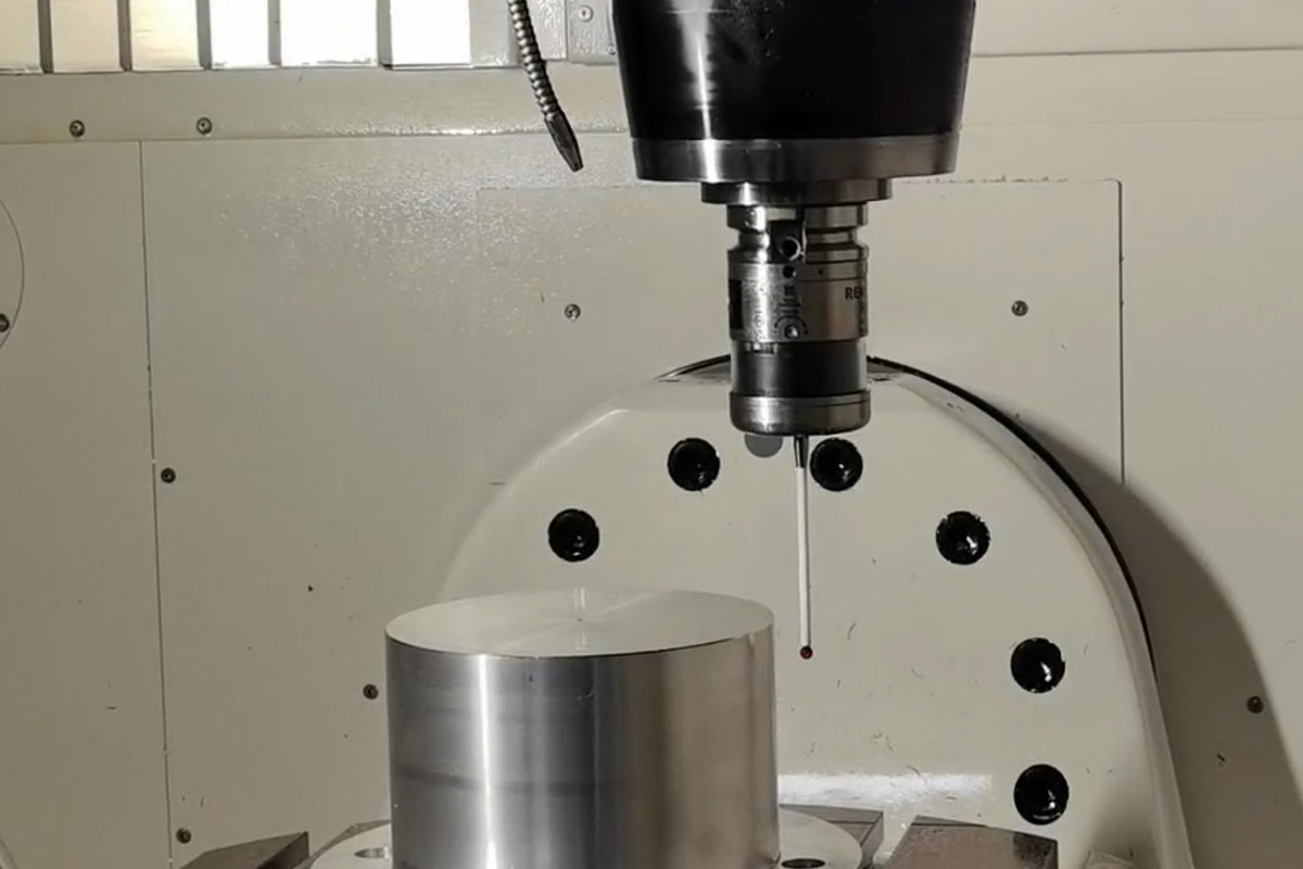
Tool Overhang Length and Clamping Runout Calibration
3. Programming and Post-Processing Verification
The post-processor file for 5-axis simultaneous action is the most prone to error in the accuracy chain. Dedicated simulation software should be used to check whether the tool tip trajectory is continuous and whether nonlinear motion causes linear axis deviation. Special validation is required to ensure that the radius error of the tool relative to the workpiece does not exceed the preset tolerance during B and C axis rotation. Enable tool swing and rotation preview functions to predict interference risks.
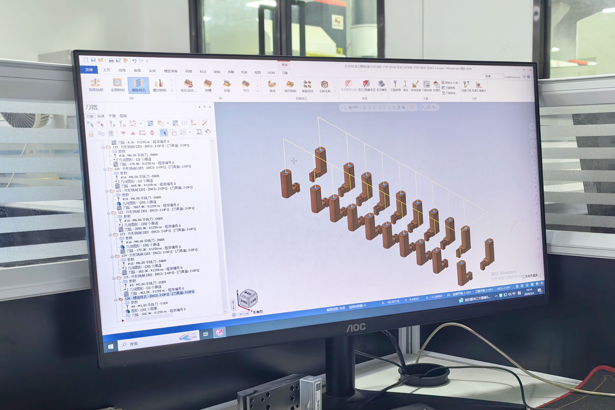
Overcut Simulation Comparison Between 3+2 and Simultaneous Programming
4. Witness Sample Accuracy Verification
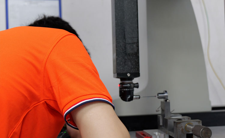
Content related to parameters such as rpm and feed rate f300mm/min is fragmented and appears to address side-wall allowance of 0.2mm to ensure maximum repeatability. Cut a digital fixture to measure its top and bottom flatness and diagonal deviation. Reserve at least two inspection cross-sections on critical groove features, and use a CMM to conduct absolute dimensional recheck.
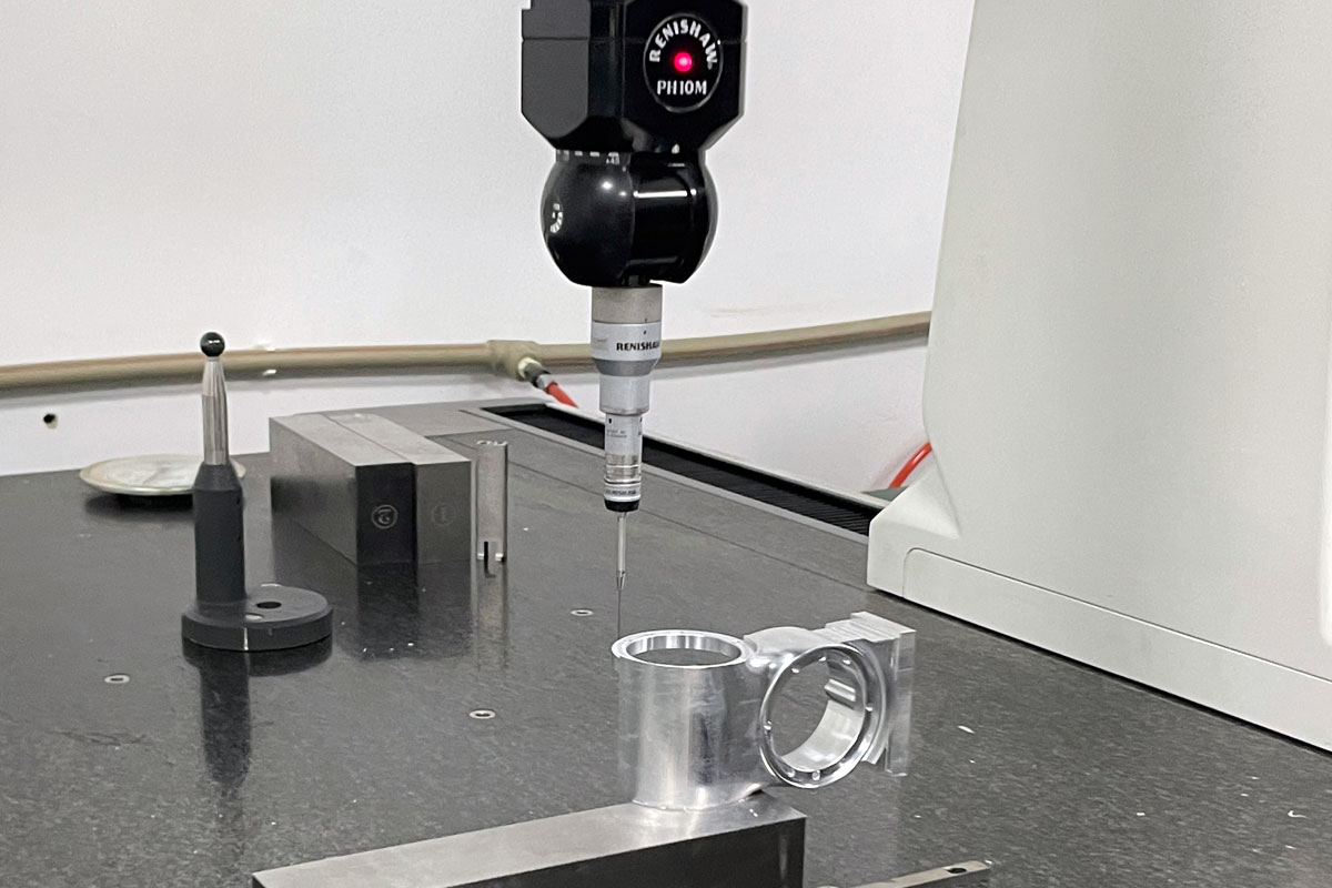
Typical Stainless Steel 304 5-Axis Verification Sample Design
5. Tolerance Assurance and Compensation Mechanism
If the deviation of a key dimension on a sample exceeds 0.04mm, immediately correct the dynamic compensation table or tool turret coordinate offset. Maintain the integrity of quality control documents, and after proactive correction, compile the blue book criteria based on the final error fluctuation (in the range of ±0.02–0.05mm). Periodically run the reverse measurement program in the zero-displacement segment under stable mechanical and temperature-controlled conditions, then proceed with precise iterations.
III. Summary and Recommendations
The capability verification of five-axis CNC machining is by no means merely a preliminary activity for initial operations; it should run through the adaptive process of any long-term production system. From roughing into finishing on solid stainless steel, establish accurate pose reference points and promptly eliminate thermal effects or accumulated clearances along the tool path. It is especially important to complete all intermediate data storage nodes to ensure smooth process reviews. It is recommended that process units establish monthly instrument inspection plans, and together with the tool tip cone angle compensation used in programming, consistently ensure the achievement of a 0.05mm mass production delivery target.
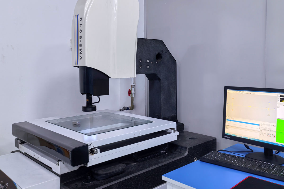
Example of a process validation control wall document
Previous:No More/End
Next:How to Avoid Deformation in Thin-Walled 6061 Aluminum Drone Parts