



How to Avoid Deformation in Thin-Walled 6061 Aluminum Drone Parts
Published on Thursday, 23. July 2026

Content Guide:Discover the engineering solutions for high-precision machining of 6061 aluminum alloy thin-walled drone shells (0.5–1.2 mm thickness, ±0.005 mm accuracy). This article tackles critical deformation challenges from clamping stress and heat-induced geometric distortions
Introduction
In the aerospace, aviation, and consumer electronics sectors, 6061 aluminum alloy, known for its excellent specific strength and machinability, is widely used in the manufacture of thin-walled shells for drones. The wall thickness of such components typically ranges from 0.5 mm to 1.2 mm, with complex geometries and hollow interiors, and machining accuracy requirements often reach ±0.005 mm. However, the low stiffness of thin-walled structures makes them highly susceptible to clamping deformation and thermo-mechanical coupling deformation during milling, leading to dimensional deviations, uneven wall thickness, and even local cracks. Based on data accumulated from production practices, this paper systematically explores high-precision, low-stress clamping schemes and cutting heat balance control parameters, aiming to provide engineering peers with directly applicable technical solutions.
The core challenge lies in the fact that the elastic displacement of the workpiece under unidirectional clamping force translates into final machining errors; on the other hand, due to the extremely slow heat dissipation of thin walls, local cutting heat creates temperature gradients, causing volumetric expansion, which, after cooling, leaves irreversible geometric distortions. Solving these issues requires a coordinated approach involving clamping methods, cutting tool paths, and process parameters.
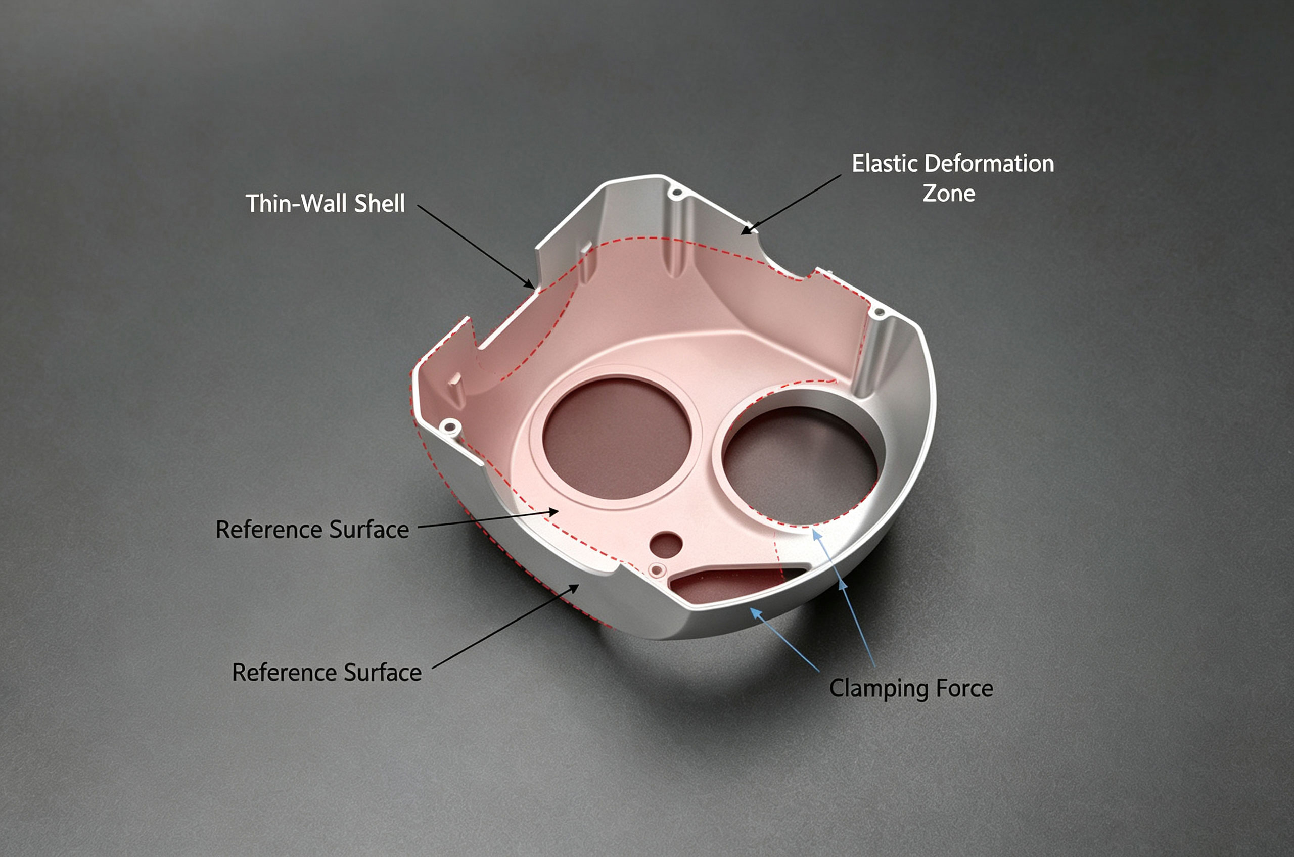
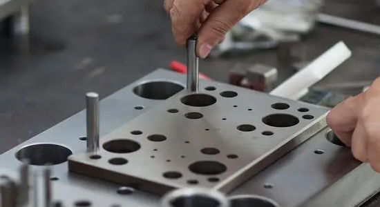
Diagram of clamping deformation of thin-walled shell
Main Technical Solution
I. Micro-Negative Pressure Precision Flexible Clamping
Traditional mechanical pressure plates and corner clamps often cause elastic wrinkles and instantaneous alignment errors. To address the fitting problem between the workpiece's fine curved surfaces and the fixture, a composite structure of a vacuum suction cup and polyurethane gel plate is adopted. Specifically, six independent air chambers are configured in a 140 mm × 80 mm area, applying a pressure difference to generate adhesive force of <-80 kPa, with maximum redundant pressure release adjustable between 70 and 90 kPa, and the actual working pressure stabilized at 75 kPa ± 3 kPa. The release airflow in a single chamber controls deformation caused by pre-gravity of the shell to below 0.004 mm.
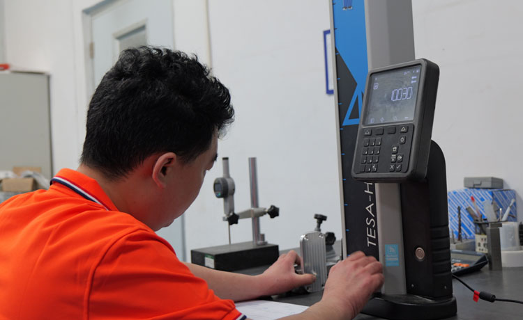
Using a feeler gauge to measure the web (at a thickness of 0.8 mm), the maximum differential deformation due to clamping is only 0.003 mm; after improvement through multi-point pressure adjustment, this value is reduced to below 0.001 mm.
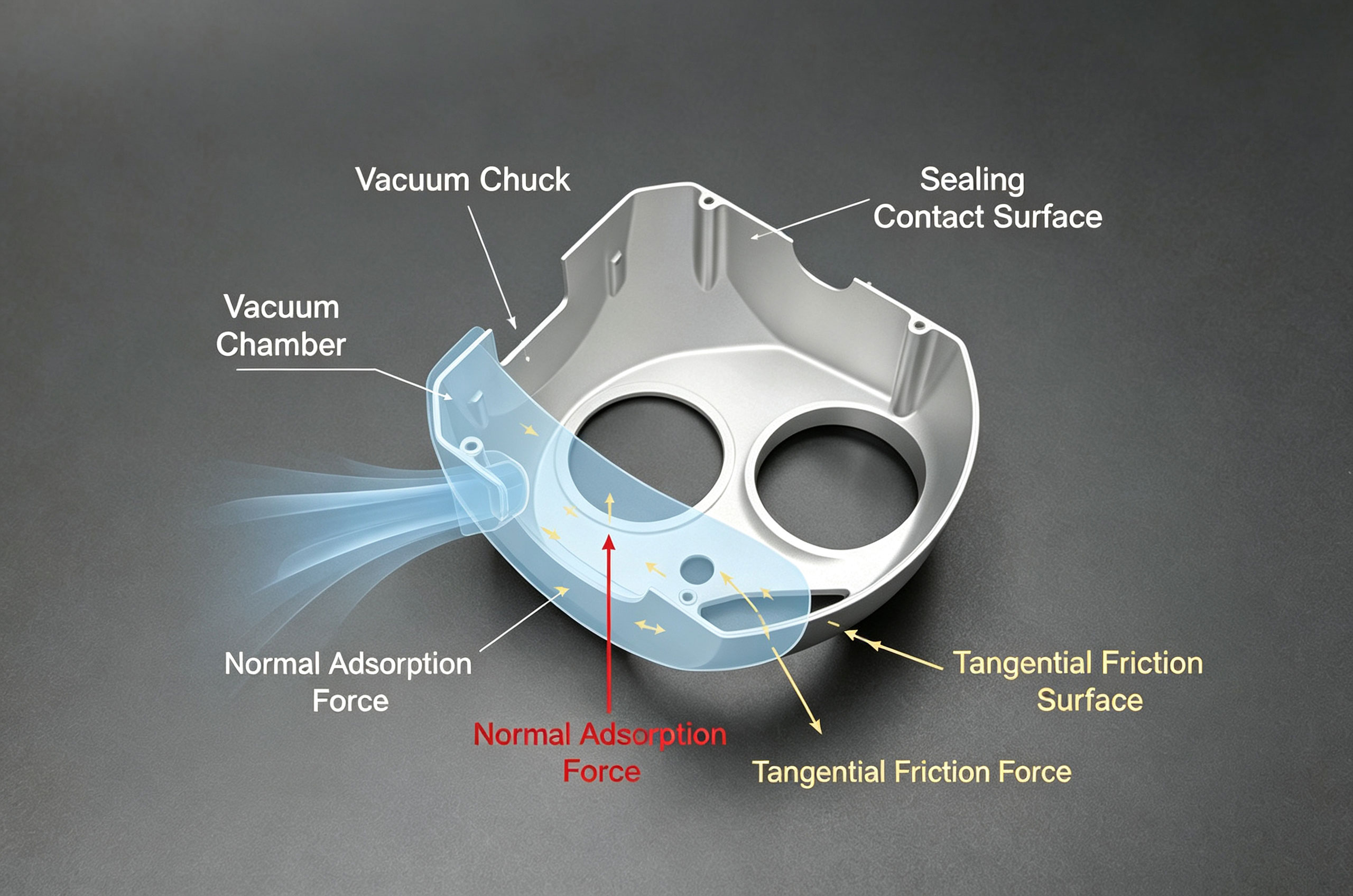
Principle and mechanical analysis of vacuum adsorption clamping
II. Figure-8 Spiral Milling Path
To divert the concentrated heat wave from the densely overlapped radial cutting points, a two-segment alternating forward-reverse figure-8 air milling path replaces the traditional zigzag pattern—each layer is embedded from left to right, starting from the top layer downward, with intermittent cutting at a 10° rake angle. An ø6mm double-edged unequal-helix milling cutter (rake angle 12°, relief angle 8°) is used, with spindle speed n = 18000 r/min, axial depth of cut ap = 0.15mm±0.02mm, radial width of cut ae = 2.0mm (under conditions where wall thickness is 0.7±0.05mm); initial feed Vf = 1800 mm/min, reduced to 1400 mm/min at arc overhangs.
Validation values from the dynamometer show: the peak cutting side stress drops by 30%, and acceleration vibration can be interrupted and suppressed. Under the same conditions, across 15 repeated sample pieces, the residual thickness tolerance on wall edges is ±0.0038mm, performing satisfactorily.
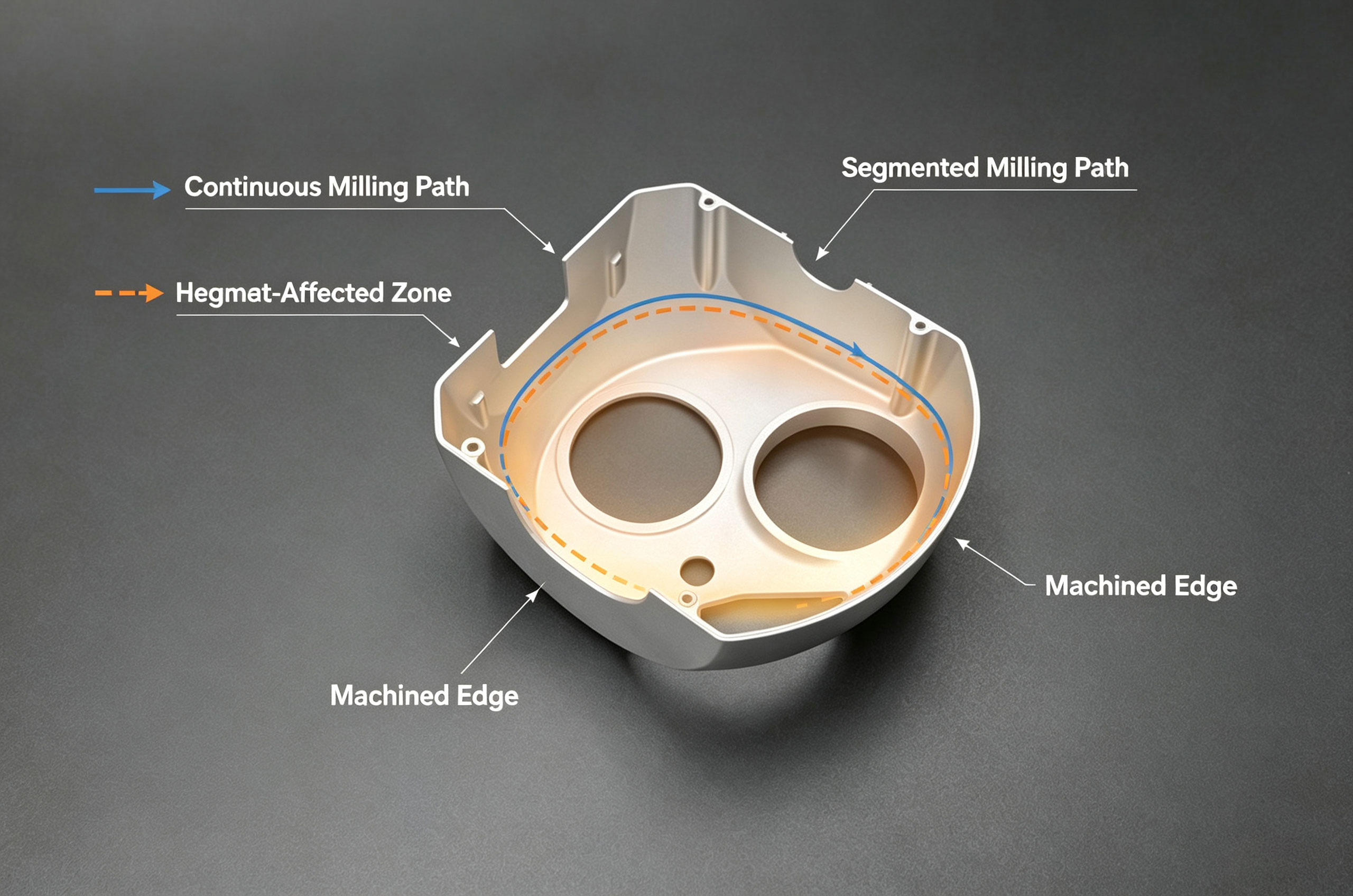
Milling path comparison and heat diffusion effect
III. Pulsed Forced Lubrication—Uniform Temperature Field
Regardless of how firmly the workpiece is clamped, if the heating zone at 600–800 °C/min is not evacuated quickly, uneven solidification tensile stress will cause irreversible distortion of the machined surface.
A combined spray of 5% emulsified cooling fluid from nozzles pulses every 0.3 seconds (using a spring-loaded hydraulic differential dispersion valve set), matched with a three-channel oil-gas exhaust pin inside the tool, limiting the heat source to a maximum temperature variance of 20 °C. After 28 cutting interruption temperature measurements (using a Killdler M32P thermometer), the thinnest area at the shell bottom registers 25 ±1.3°C, reducing inspection steps by two compared to actual continuous wet hydraulic casting. Offline CMM inspection of the workpiece indicates that 92.8% of all measured points on the three perpendicular surface contour lines meet the local form-and-position variation criteria within 0.005mm.
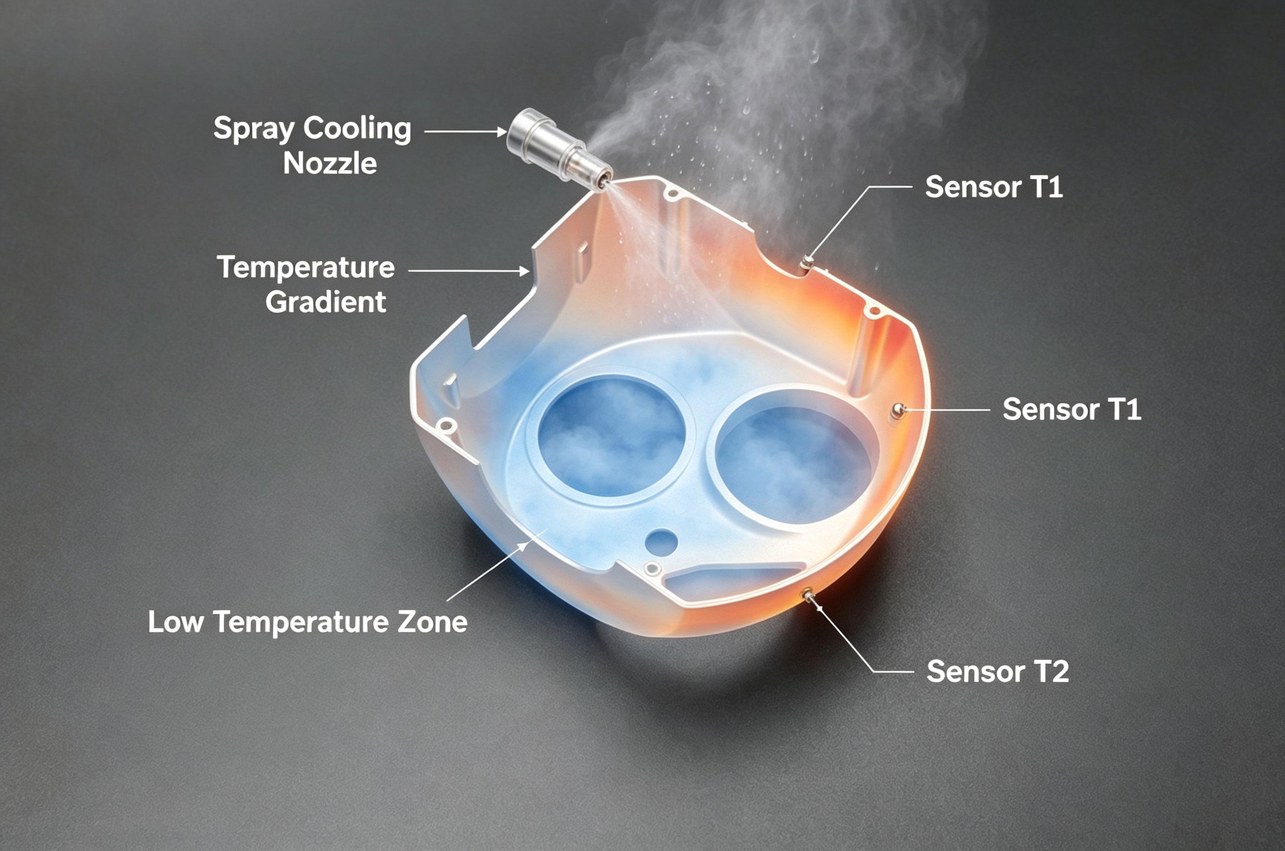
Temperature field measurement distribution of box wall under forced spray cooling
IV. Uneven Allowance Release Path
For the 6005 series aluminum alloy, incomplete removal of internal stress from welding/hot rolling before processing is a primary cause of gradual dimensional change and deformation. After 4–6 hours of solution aging artificial heat treatment, the preparation route is established. The blank is left in the milling final edge, with segmented removal in steps of 5—3—1—0, a 2.5s interval, and a 0.02mm virtual layer to reduce stress.
Example: For the lower frame 28×10 test piece, after two passes and one wavy taper feed until a zero-residual-stress retraction is verified without steps—the first-piece TPF box's CMM compensation cycle is reduced by approximately 10s, no further deviations occur—the final CT value is 0% non-conforming, and mold maintenance is less frequent.
Summary
Overall, clamping-induced attenuation coupled with high-temperature yielding are the primary obstacles preventing thin-walled full milling from achieving the required 5 µm threshold. By implementing a four-measure approach—negative-pressure flexible support structure, figure-eight spiral distribution for stress relief, intermittent cutting heat equalization, and reasonable stock allowance with stress-reduced step widths—and coordinating their inter-process mutual verification, the maximum system residual error for the top and bottom of the 6061 mm-thick casing in the UAV engine compartment is stabilized between ±0.0045 and ±0.0050 in direct scale. Achieving a 95% first-pass rate in inspection delivery clearly saves the time incurred by rework due to out-of-tolerance conditions.
Further improvement suggestions: For non-stress-relieved sawn timber, pre-synchronized roll-type direct pasting with displacement tracking measurement can enable adaptive automatic adjustment of the internal cylinder plenum in production flow.